SEEING WITH LASERS
LiDAR is an acronym for “light detection and ranging,” (sometimes Light Imaging, Detection, And Ranging). Like sonar and radar, LiDAR relies on the same principle: echolocation.
Although it sounds like Star Wars space science, echolocation has been around for millions of years and happens to be a critical tool for a little flying mammal – the humble bat. Bats use sound waves — issuing a squeak that bounces off an object that returns to their ears sooner or later depending on how far away the object is. Tracking how long it takes to come back tells the bat the distance and location of prey—or death by tree.
Fast forward to naval sonar, which sends a bigger click into the surrounding water and listens for echoes. Knowing how fast sound travels in water, operators can tell exactly how long it took to hit something and come back, telling them precisely how far away it is.
Radar, the next big advance, does much the same thing with radio waves. The familiar radar dishes we’ve all seen fire out a beam of radio waves. When those waves hit something solid they bounce back and the dish detects them. Since we know the exact speed of light we can calculate the distance of the object hit. But radio waves have limitations. They don’t detect some objects, and don’t work well below an elevation of 100 feet.
HIGH PRECISION OPTICAL DISTANCE MEASUREMENT
LiDAR systems use lasers to send out pulses of light outside the visible spectrum and measure how long it takes each pulse to return. When it does, the direction of and distance to whatever that specific pulse hit, is recorded as a point in a 3D map with the LiDAR unit at the center. Starting in the early 1960s, laser-focused imaging (with the ability to calculate distances by measuring the time for a signal to return) and data acquisition electronics were combined.
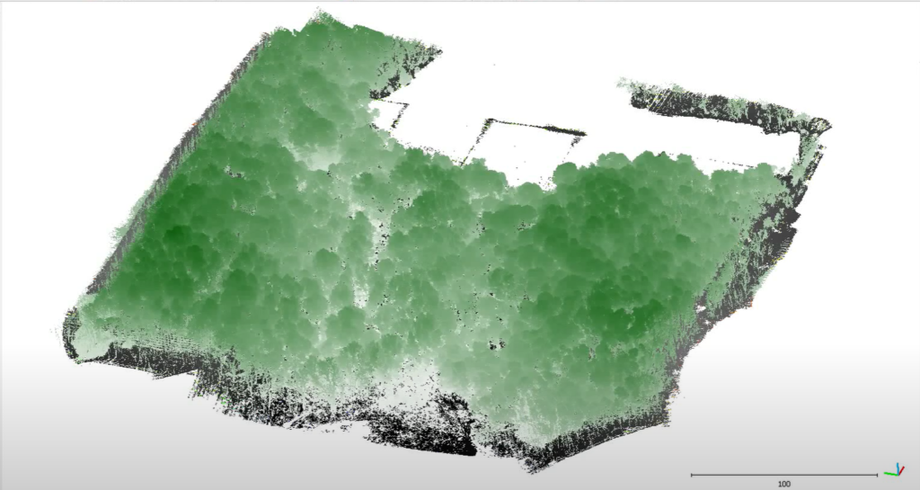
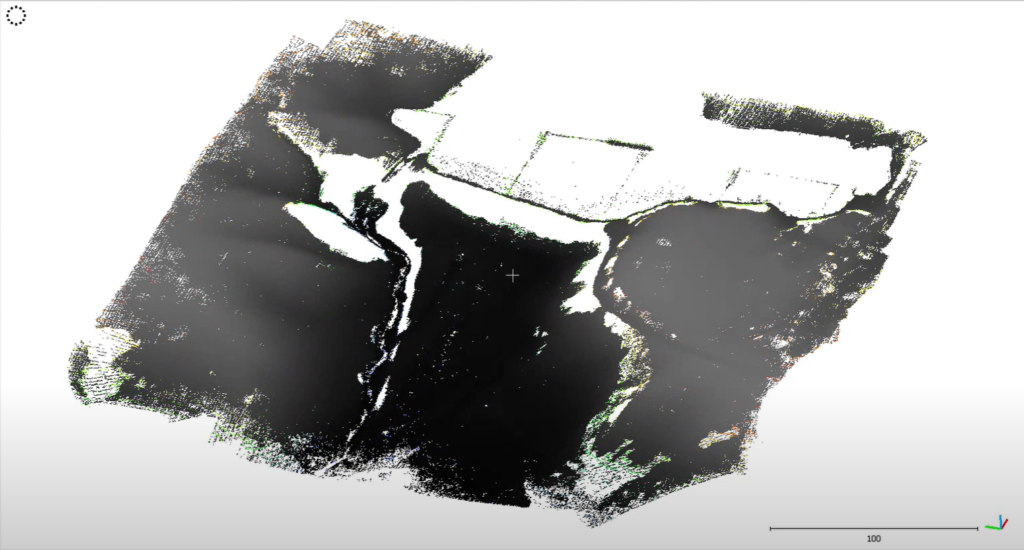
Today, thanks to shrinking electronics and the great speed of computers, a LiDAR imaging system may send out and receive millions of pulses and complete hundreds of revolutions per second. The resulting “point cloud,” a collection of coordinates from returning laser pulses, can be extraordinarily detailed showing all the contours of the environment and objects within it.
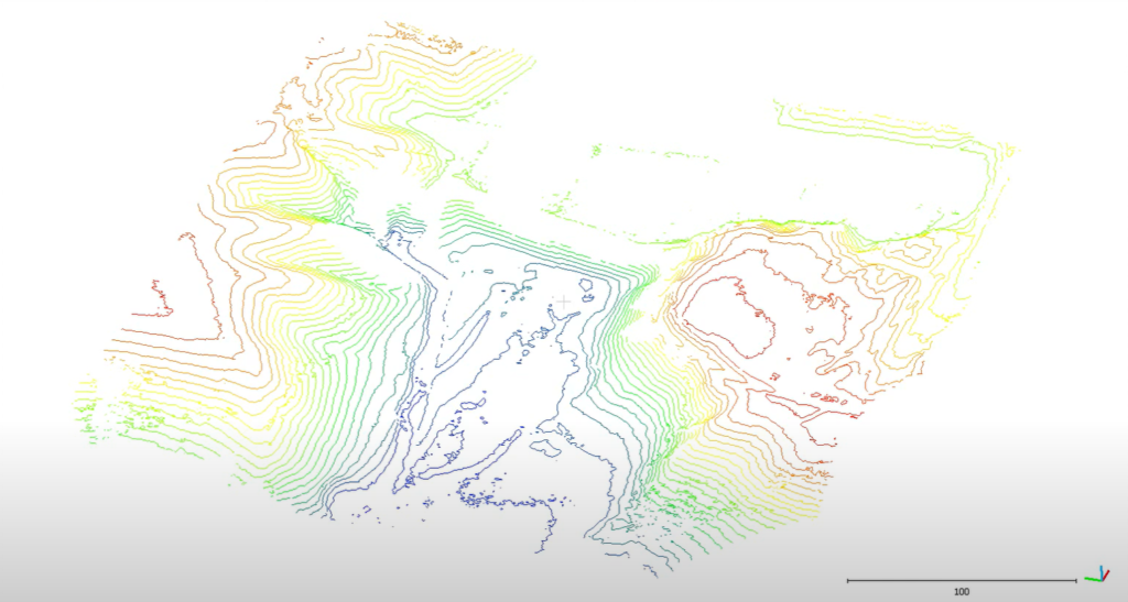
LiDAR, which provides rapid, remote data sensing solutions, is popularly used to make high-resolution maps with applications in geomatics, archaeology, geography, seismology, forestry, atmospheric physics, laser guidance, and airborne laser swath mapping (ALSM), to name a few. This is just the beginning.